
Load Weighing Devices
LWD for under motor bedframe BPP
BPP, BPP-CB undercabin sensor introduction The BPP and BPP-CB sensors are designed for installation and operation under the engine compartment, the capacity of this sensor is 3000 kg (cabin capacity + cabin weight), which is connected to…
Catalogs & documents
Use the continuous web edition for reading, search and source-page references. The original file remains available on every document page.
Product information
Specifications
BPP, BPP-CB undercabin sensor
introduction
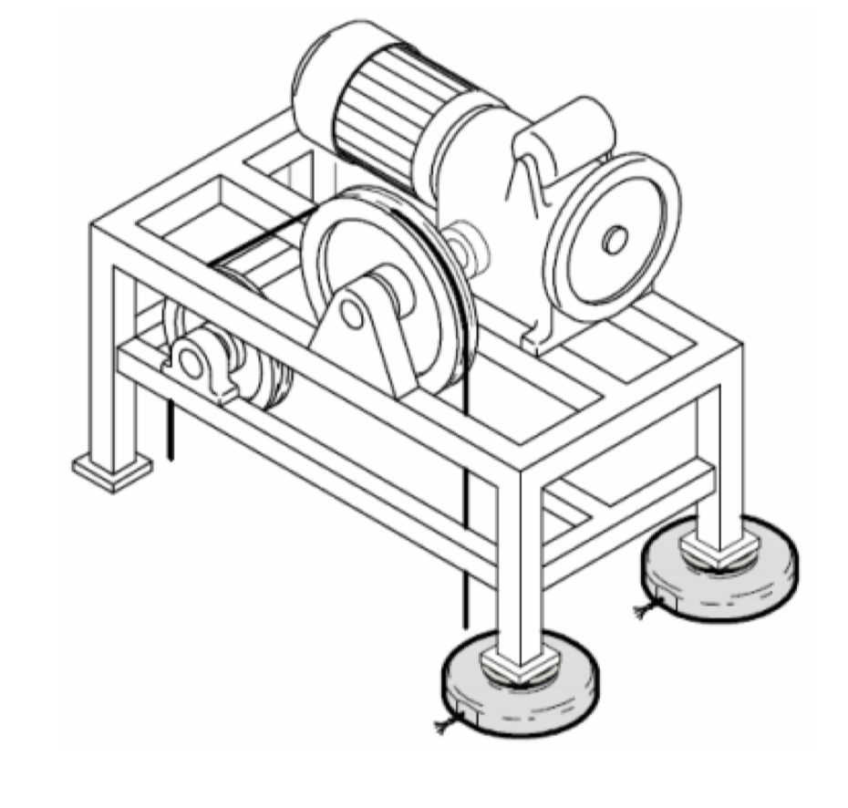
The BPP and BPP-CB sensors are designed for installation and operation under the engine compartment, the capacity of this sensor is 3000 kg (cabin capacity + cabin weight), which is connected to the VK or RCU control device by a 5-meter cable. In order to measure the weight with high accuracy, two sensors under the engine shaft should be used, in fact, two sensors work with a double capacity, i.e. 6000 kg.
The way this sensor works is that two sensors under the chassis of the engine are installed on the side of the cab axles, instead of the bumper tires, and measure the pressure from the engine chassis and compare it with the weight introduced during the adjustment and measure the weight inside the cabin. The difference of the CB model is in the design of this sensor, as you can see in the picture, BPP-CB can be screwed to the engine shaft, and due to the designed plate under the sensor, the transfer of vibrations has been prevented and the installation of the sensor has been made easier. It is recommended to use this sensor in projects with high capacity and stoppage, where it is not possible to use the under-cabin sensor.
Features
• Made by Dinasel Spain
• European Union standard
• Has 1 year warranty
• 5 years after-sales service
• 24-hour service and support
• Weight measurement and loading restrictions
• The sensor is installed under the motor shaft and the controller inside the panel
• Very easy setting (Persian catalog of setting)
• Advanced design to prevent transmission of mechanical vibrations
• Weight holder inlet during cabin movement
• Two sensors should be used to achieve optimal accuracy
• Up to 4 sensors can be connected in parallel to a control unit
• "Automatic calibration" without the need to perform a step (specific weight) for final adjustment
Electrical specifications
• Can be connected to VK and RCU 205 control device
• Very low energy consumption of the RCU 205 control device (2 W energy consumption)
• The control device RCU 205 is very low cost and optimal
• The VK control device has 3 output relays and the RCU 205 control device has 2 output relays
• Serial communication capability on the VK device (optional)
• It has 3 indicator lights of the weight range on the VK device (optional)
• Cabin display output on VK device (optional)
• Analog output on VK device (V, 4 to 20 mA 10 to 0) (optional)
• Very easy wiring and adjustment (Persian catalog of adjustment)
• RCU 205 controller input power source (24 V-DC)
• VK controller input power supply (115~230V-AC)
• Nominal frequency 50 to 60 Hz
• Contact relays V - 3 amps 250
• The input voltage of the holder is 24V ~ 230V - AC / DC
• Device protection class V0 IP-50, fireproof plastic
• Specifications of different models of controller devices
In the same category
Related Products

لودسل دیناسل
OMEGA 800 R Load weigh device
OMEGA 800 towing tension sensor introduction Sensor RTM Dinasel Company (Dinasel) is specially designed to control, adju
Details & documents
لودسل دیناسل
Rope loadcell LCK ng
LCK ng cable sensor introduction The new generation of sensors of Dinasel Spain company with dongle (WRCT NG) and Dinase
Details & documents
لودسل دیناسل
OMEGA ng load control unit
Towing tension sensor introduction The OMEGA-RT NG controller device is specially designed to adjust and monitor the ten
Details & documents